
If you’ve been working on raspberry pi for some time now, you must be thinking about how to make it useful in real world applications, right?
Real world applications, where raspberry pi can turn on / off a device by receiving commands either from internet of via some sensors or via a mobile phone application talking to pi using Bluetooth. The possibilities are literally limitless if we know how to perform this.
In this tutorial, we’re going to see exactly how we can interface a real world device with raspberry pi to perform switching.
Switching Devices with Raspberry Pi
If you’ve experimented on raspberry pi, then you must know that raspberry pi has a GPIO, meaning general purpose input/output port pin.
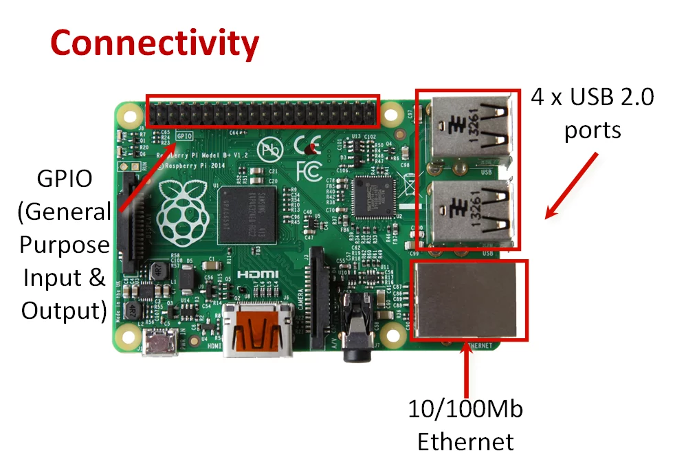
As you can see in the above image, the 40-pin GPIO is useful to interface a wide variety of output devices. Raspberry Pi being a digital computer, can generate logic outputs on the GPIO pins. These logic output is called as logic 0 and logic 1. Practically, when writing a program for writing logic 0 on the pin of raspberry pi, an actual 0 volt or GND potential appears on the pin. Similarly, when writing logic 1 on the pin, a +3.3V appears on the pin of Raspberry pi.
By writing a program we can generate logic 0 (gnd) or logic 1 (+3.3v) on any output pin of raspberry pi. But this output voltage is very low to turn on any physical devices. In fact the 3.3V generated on output pin is also current limited so it cannot deliver more than 20 mA current from that pin. It means, we can interface an LED directly to raspberry pi gpio pin, and thats about it. You can’t connect any other output device directly to the pin of raspberry pi, not even a DC motor. So connecting an AC Device needs something different.
Relay as Switching Circuit

As said before, raspberry pi is a digital computer and the output is confined between +3.3v and 0v output levels. Therefore, we need an electronic switching circuit in order to connect any physical device to raspberry pi to perform switching. For the entire discussion of this tutorial, lets assume that we want to connect a Lamp to raspberry pi and make it On / Off. We cannot connect bulb directly to raspberry pi and hence we need a switching circuit. To switch On / Off AC devices, we need a switching circuit like relay.
A relay is an electromagnetic switch which works on DC voltage and can turn on AC as well as DC devices. The internal construction of relay looks like below schematic
as
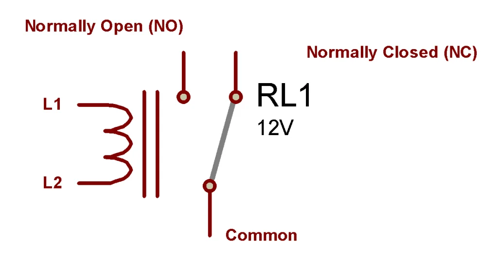
As can be seen in above image, a simple relay is having 5 terminals
L1 and L2 are the points of an eletro-magnetic coil which acts as a magnet inside relay. The L1 / L2 can be connected directly to a DC voltage source. Whenever the coil is given with voltage, it acts as an electromagnet.
The terminal Common is a movable terminal and NC (normally closed) and NO (Normally open) are fixed terminals.
Working of Relay
The Common terminal is residing on NC terminal using a sprint tension. This is default condition of relay. If a relay is placed on a table, then the NC and COM terminals are connected to each other. Whenever the coil voltage is applied between L1 and L2, the coil gets magnetized. Due to this magnetism, the common terminal is pulled away from NC and now resides on NO. There by acting against spring tension due to magnetism. As long as relay is energized, the situation remains the same and NO and COM are connected. Whenever the relay is turned off by removal of the coil voltage, then magnetism is finished and common terminal goes back to NC Terminal
See this short gif here

Now as you can see, if we can properly switch On / Off relay, we can connect any AC device and make it switch along with relay. But the question is how to turn on relay itself. Most relay’s work on 12v or 24v and raspberry pi can’t generate that voltage. There are relays who work on +5v coil voltage also, but they need about 30-50mA current which any microcontroller cannot provide. Therefore we cannot directly connect relay to raspberry pi and hence, we need a switching circuit for relay itself.
Transistorized Switching Circuit for relay
For switching any DC load using raspberry pi or similar microcontroller signal, we can use transistorized switching circuits. More details about transistors can be read here
In order to use transistor for switching relay with raspberry pi, here’s the full circuit here
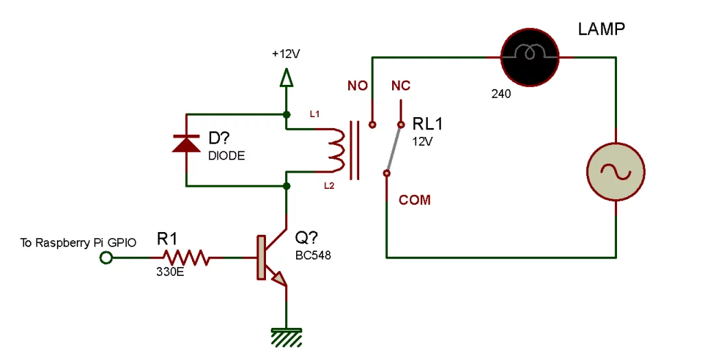
As shown in above circuit. The transistor is used to perform switching of relay coil and the relay terminals are used as switching points for AC Load. Using above circuit, you can connect any AC load to raspberry pi and make the device ON or OFF.’
The Components used here are
- Q1 = NPN transistor, any normal will do, we’ve used BC548
- R1 = 330 ohm resistor
- D1 = simple switching Diode like 4148
- RL1 = 12v Relay
As seen in above diagram, the Diode D1 is used as a protection device which facilitates the easy turn off of the relay.
The output form raspberry pi pin will go directly to the resistor connected to the base of transistor. Whenever the output is made HIGH, the relay will turn ON, and whenever the output is made LOW, the relay will turn OFF, here’s a program
led1 = 21 #GPIO pin to connect to relay
import RPi.GPIO as GPIO
import time
GPIO.setmode(GPIO.BCM)
GPIO.setup(led1, GPIO.OUT)
while True:
    GPIO.output(led1, True)
    time.sleep(2)
    GPIO.output(led1, False)
    time.sleep(2)
Relay Module
Currently, instead of making this entire circuit all by yourself, we get a direct relay module in many online stores, it looks like this

All we have to do here is give the rated voltage from power supply to this relay module and then connect the signal pin to GPIO of raspberry pi. All the related transistor and switching circuit is already present on this board. While using such relay module, just make sure that the GND of the power supply which gives power to relay module (5v/12v/24v) and the GND of raspberry pi should be made common. Means they should be connected to each other.
A simple demonstration of relay working with a lamp is shown in below video
Let me know in the comments if it was easy to understand or did you faced any difficulty in interfacing with your relay module with Pi
