How to Install OpenCV on Raspberry Pi 5
How to install OpenCV on raspberry Pi 5 computer python library
How to install OpenCV on raspberry Pi 5 computer python library
Optocouplers, also known as opto-isolators, are electronic components that provide electrical isolation between two circuits by using light to transfer signals. Optocouplers are commonly used to protect sensitive electronic devices from voltage spikes, reduce noise and electromagnetic interference, and provide isolation in high-voltage applications. Raspberry Pi Pico is a popular microcontroller board that features a … Read more
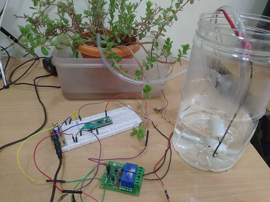
Introduction This is a detailed project documentation for one of the videos we published on youtube. This is about making an IOT plant watering system using raspbery pi pico w Components required 1) Raspberry Pi Pico W board 2) Relay 3)Usb Cable for program downloading 4) DC Power supply 5v and 12v 5)Water pump 5v … Read more
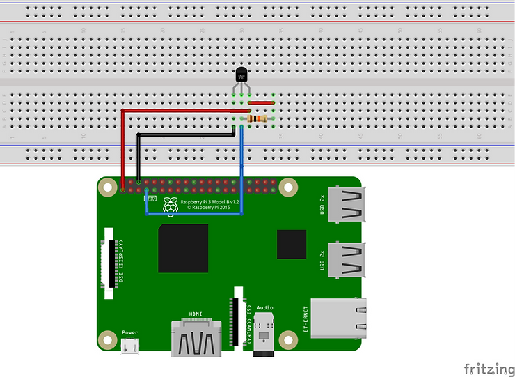
Data Logger Using DS18B20 Temperature Sensor With Raspberry Pi Introduction In this tutorial we are going to learn how to make Data Logger with csv file extension by using DS18B20 Temperature Sensor With Raspberry Pi Component Required Raspberry Pi Board Breadbord Power supply DS18B20 Temperature sensor 10 Kilo Ohm Resistor (pull up) Breadbord Connecting Wires … Read more
C# Console program to test the connection of windows pc to MYSQL on Raspberry Pi

How to connect to mysql on raspberry pi from windows computer
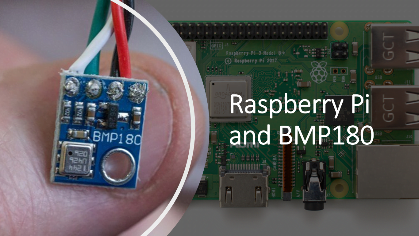
This is an in depth tutorial on how to interface raspberry pi with BMP180 Sensor. This is an I2C Based sensor and we’ll see how to interface with I2C sensor with this tutorial
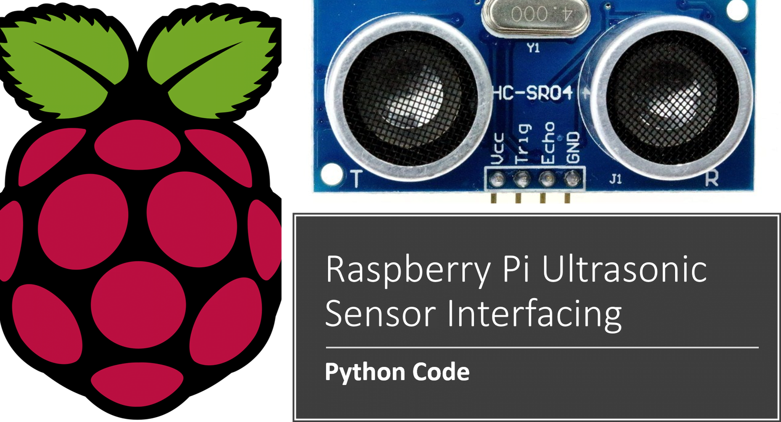
A detailed tutorial about Raspberry Pi interfacing with Ultrasonic Distance sensor and its python code

This tutorial is about interfacing of relay with raspberry pi for switching ac and dc devices on and off
Raspberry Pi Streaming Video Setup If you do not already have pip installed on your Raspberry Pi, please use this command to install it: sudo apt-get install python-pip Install the picamera library by running this command: pip install picamera Install the flask Python library by running this command: sudo pip install flask Download Miguel’s Flask … Read more

Learn how to use mqtt with raspberry pi and write program to perform mqtt communication in python

Python program to send emails from raspebrry pi with and without attachments
Know whats the difference between Raspeberry pi 3 and Raspberry pi 4

What is Raspberry Pi? We’ve all heard about raspberry pi, haven’t we? But there are many questions in every hobbyist and engineers mind about raspberry pi, for example What is exactly raspberry Pi? Why raspberry pi is used for? Is raspberry pi a processor/micro controller/ OS? I’ve bought a raspberry pi, whats next?? And Most … Read more
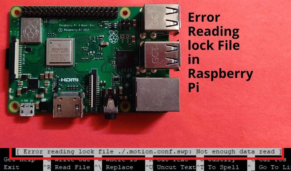
Many times, it happens while using raspberry pi that we’re not able to edit some particular files. For me it has happened with Motion.conf file, which is used to configure the video streaming service called motion on raspberry pi Rc.local, this file resides in /etc and is used for adding commands to run programs on … Read more
