How to use bluetooth with 8051

How to use bluetooth with 8051

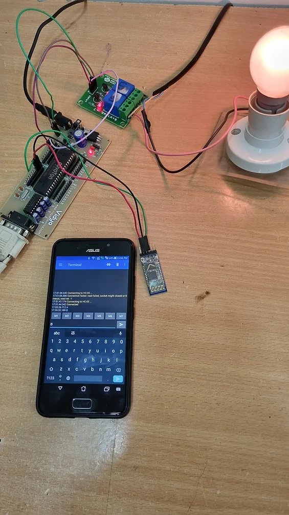
This Project is Suitable for Everyone Including student and Professional

Bluetooth-based relay control using an 8051-based microcontroller involves using Bluetooth communication to remotely control the switching of a relay. Here’s a general overview of the system:

  1. Hardware components:
  • 8051-based microcontroller board
  • HC-05 Bluetooth module
  • Relay board
  • Power supply
  • AC Bulb 230v
  • Bulb Holder
  • Android based Mobile phone

  1. Connections:
  • The HC-05 module is connected to the microcontroller’s serial port pins.
  • The relay board is connected to the microcontroller’s output pins.
  • Power supply connections are made to power the microcontroller and the relay board.
  1. Software:

The software for this system involves two main parts:

  • Code for the microcontroller to receive commands from the Bluetooth module and switch the relay on or off accordingly.
  • An Android application to send Bluetooth commands to the HC-05 module.
  1. Operation:
  • The Android application sends Bluetooth commands to the HC-05 module.
  • The HC-05 module receives the commands and sends them to the microcontroller.
  • The microcontroller interprets the commands and switches the relay on or off based on the command received.

Overall, this system provides a wireless means of controlling a relay, which can be useful for a variety of applications, such as home automation or industrial control systems.

#include<reg51.h>  
sbit X = P1^0;      // connect relay1 to P1.0
sbit Y = P1^1;      // connect relay2 to P1.1

void delay(unsigned int count)
{
    unsigned int i;              
    while(count)
    {
        i = 115;
        while(i > 0)
        i--;
        count--;
    }
}
/*
Uart initialization function, call this function by passing a valid baud rate value to initialize UART
currently Supported Baud Rates are 9600,4800,2400,1200
*/
void uart_init(unsigned int baud)
{
    unsigned int a = 9600, b = 4800, c = 2400 , d = 1200;   

    TMOD = 0x20;    // timer 1 8-bit auto-reload
    SCON = 0x50;    // Tx and Rx enable     

    if(baud == a)
    {
        TL1 = 0xFD; 
        TH1 = 0xFD; 
    }
    if(baud == b)
    {
        TL1 = 0xFA; 
        TH1 = 0xFA; 
    }
    if(baud == c)
    {
        TL1 = 0xF4; 
        TH1 = 0xF4; 
    }
    if(baud == d)
    {
        TL1 = 0xE8; 
        TH1 = 0xE8; 
    }
    
    TR1 = 1;        // Start timer
}

/*~~~~~~~~~~~~~~~~~~~~~~~~~~~~~~~~
    Trasmitting 8 bit data
Send 8-bit data while callinjg this function
to send it over UART
~~~~~~~~~~~~~~~~~~~~~~~~~~~~~~~~*/

void uart_write(unsigned char value)
{
    SBUF = value;
    while(!TI);
    TI = 0;
}

/*~~~~~~~~~~~~~~~~~~~~~~~~~~~~~~~~
    Receiving 8-bit data
~~~~~~~~~~~~~~~~~~~~~~~~~~~~~~~~*/

char uart_read()
{
    while(!RI);
    RI = 0;
    return(SBUF);
}

/*~~~~~~~~~~~~~~~~~~~~~~~~~~~~~~~~
    Xmitting String
~~~~~~~~~~~~~~~~~~~~~~~~~~~~~~~~*/

void uart_write_text(char *str)
{
    unsigned char i=0;
    while(str[i])
        uart_write(str[i++]);
}


/*~~~~~~~~~~~~~~~~~~~~~~~~~~~~~~~~
    Read a particular number of bytes in a string
~~~~~~~~~~~~~~~~~~~~~~~~~~~~~~~~*/
void uart_read_text(void *buff, unsigned int len)
{
    unsigned int i;
    for(i=0;i<len;i++)
    {
        ((char*)buff)[i]=uart_read();
    }
}

/*~~~~~~~~~~~~~~~~~~~~~~~~~~~~~~~~
    Echoing received data
~~~~~~~~~~~~~~~~~~~~~~~~~~~~~~~~*/
void uart_echo()
{
    uart_write(uart_read());
}


void main()
{   
    unsigned char byte;
  uart_init(9600);
    
    //P2 = 0x00;
    
     X=0;
     Y=0;
     
    delay(100);
    uart_write_text("Welcome");
    while(1)
    {
          byte = uart_read();           // receive a byte serially, wait 1 second and again send it back
            if(byte == 'A')
            {
                X = 1;
            }
            if(byte == 'a')
            {
                X = 0;
            }
            if(byte == 'B')
            {
                Y = 1;
            }
            if(byte == 'b')
            {
                Y = 0;
            }
            
          delay(100);                       //  little delay so that user can recognize it
          uart_write(byte);             // resend received data over UART
    
    }
}

for more learning of Python Raspbery Pi, Internet of things , ESP 32 ,and Arduino click on courses

How To Interface Seven Segment Display With 8051 Microcontroller

How To Interface Seven Segment Display With 8051 Microcontroller

Introduction:

Seven-segment displays are commonly used to display numbers and characters in various electronic devices. They are easy to read, low-cost, and consume very little power. Interfacing a seven-segment display with a microcontroller like the 8051 is a simple task that can be accomplished with minimal hardware and software requirements.

In this blog post, we will discuss the basics of seven-segment displays and how to interface them with an 8051 microcontroller.

What is a Seven-Segment Display?

A seven-segment display is a display device consisting of seven LEDs arranged in a specific pattern to display numerals and some letters or symbols. Each of the seven LEDs can be controlled independently to display different combinations of characters. By turning on or off the appropriate LEDs, it is possible to display all the numbers from 0 to 9 and some letters like A, b, C, d, E, F.

The seven segments are labeled as A, B, C, D, E, F, and G. Each segment is connected to a different pin of the display. In addition, there is an eighth pin that controls the decimal point.

Interfacing a Seven-Segment Display with 8051: To interface a seven-segment display with an 8051 microcontroller, we need to connect the segments of the display to the output pins of the microcontroller. We also need to connect the common cathode or anode of the display to a suitable voltage source, depending on the type of display.

For a common cathode seven-segment display, we need to connect the common cathode pin to ground and the segment pins to the output pins of the 8051. For a common anode display, we need to connect the common anode pin to Vcc and the segment pins to the output pins of the 8051.

Once the display is connected to the microcontroller, we can write a program to control the display. We can use the P1 port of the 8051 to connect to the segment pins of the display. To display a number, we need to send the appropriate combination of signals to the segment pins. For example, to display the number 0, we need to turn on all the segments except G. Similarly, to display the number 1, we need to turn on only segments B and C.

Circuit:

Note : in above circuit diagram connect reset circuit to pin number 9 and crystal oscillator 11.0592 to Pin number 18 and 19

Code Example: Here is an example program to display the numbers 0 to 9 on a common anode seven-segment display connected to the 8051 microcontroller:

                  
**************************************************************
#include <reg51.h>
#define SEG_PORT P1

void delay(unsigned int count) {
  unsigned int i, j;
  for(i=0; i<count; i++) {
    for(j=0; j<1275; j++);
  }
}

void display(unsigned char num) {
  switch(num) {
    case 0: SEG_PORT = 0xC0; break;
    case 1: SEG_PORT = 0xF9; break;
    case 2: SEG_PORT = 0xA4; break;
    case 3: SEG_PORT = 0xB0; break;
    case 4: SEG_PORT = 0x99; break;
    case 5: SEG_PORT = 0x92; break;
    case 6: SEG_PORT = 0x82; break;
    case 7: SEG_PORT = 0xF8; break;
    case 8: SEG_PORT = 0x80; break;
    case 9: SEG_PORT = 0x98; break;
    default: SEG_PORT = 0xFF; break;
  }
}

void main() {
  unsigned char i;
  while(1) {
    for(i=0; i<=9; i++) {
      display(i);
      delay(500);
    }
  }
}

In this code, we define the SEG_PORT pin using a #define statement. We also define a delay function to add some delay between the display of each number. The display() function is used to display a number on the seven segment display. We use a switch statement to determine which segments of the display need to be lit up for each number. Finally, in the main function, we use a for loop to continuously display numbers 0-9 on the seven segment display, with a delay of 500ms between each number. The while(1) loop is used to keep the program running indefinitely.

Note that this code assumes that the seven segment display is connected to the 8051 microcontroller as follows: the common anode pin is connected to ground, and the 7 segment pins (A-G) are connected to P1. You may need to modify these pins depending on your specific hardware configuration

LCD Interfacing With 8051Microcontroller in 4 Bit Mode

LCD Interfacing With 8051Microcontroller in 4 Bit Mode

Introduction

Interfacing an LCD (Liquid Crystal Display) to a microcontroller is a common task in embedded systems design. we are making its simplicity and ease of use. In this blog post, we will discuss how to interface an LCD to an 8051 microcontroller in 4-bit mode.

LCD Basics

LCD is a display that uses the properties of liquid crystals to produce an image. It consists of an array of pixels that can be individually controlled to produce text and graphics. The most commonly used type of LCD is the character LCD, which displays characters and symbols in a fixed format.

LCD requires a minimum of 7 pins to interface with a microcontroller: RS, RW, E, and 4 data pins. RS (Register Select) and RW (Read/Write) pins are used to select between data and command modes and to control the direction of data flow. The E (Enable) pin is used to trigger the LCD to latch in data. The 4 data pins are used to send the 4-bit or 8-bit data to the LCD.

Interfacing an LCD to 8051 Microcontroller

follow these steps:

1.Connect the power supply: An LCD requires a power supply of +5V and 0V. The +5V can be obtained from the 8051 microcontroller’s Vcc pin, and 0V can be obtained from the GND pin.

2.Connect the control pins: Connect the RS, RW, and E pins of the LCD to the 8051 microcontroller’s GPIO pins. Set the RS pin to 0 for command mode and 1 for data mode. The RW pin should be set to 0 to write data to the LCD. The E pin should be pulsed high and low to trigger the LCD to latch in data.

3.Connect the data pins: Connect the 4 data pins of the LCD to the 4 GPIO pins of the 8051 microcontroller. We are using 4-bit mode for this example, so we only need to connect the 4 least significant data pins (D4-D7) of the LCD to the GPIO pins of the 8051 microcontroller.

4.Initialize the LCD: To initialize the LCD, we need to send some commands to it.

The following commands are commonly used:

a. Function Set: This command sets the interface data length, number of display lines, and font size. The command is 0x28 for 4-bit mode.

b. Display ON/OFF: This command turns the display on or off. The command is 0x0C for display on and 0x08 for display off.

c. Clear Display: This command clears the display and sets the cursor to the home position. The command is 0x01.

5.Write data to the LCD: To display data on the LCD, we need to send the data to it. We set the RS pin to 1 to select data mode and the RW pin to 0 to write data. We then send the data in 4-bit mode, one nibble at a time. We pulse the E pin high and low after each nibble to latch in the data.

#include <reg51.h>

#define RS P1_0
#define RW P1_1
#define E P1_2
#define LCD_PORT P2

void delay(unsigned int count) {
  unsigned int i, j;
  for(i=0; i<count; i++) {
    for(j=0; j<1275; j++);
  }
}

void lcd_cmd(unsigned char cmd) {
  LCD_PORT = (LCD_PORT & 0xF0) | ((cmd >> 4) & 0x0F);
  RS = 0;
  RW = 0;
  E = 1;
  delay(5);
  E = 0;
  delay(5);
  LCD_PORT = (LCD_PORT & 0xF0) | (cmd & 0x0F);
  E = 1;
  delay(5);
  E = 0;
  delay(5);
}

void lcd_data(unsigned char data) {
  LCD_PORT = (LCD_PORT & 0xF0) | ((data >> 4) & 0x0F);
  RS = 1;
  RW = 0;
  E = 1;
  delay(5);
  E = 0;
  delay(5);
  LCD_PORT = (LCD_PORT & 0xF0) | (data & 0x0F);
  E = 1;
  delay(5);
  E = 0;
  delay(5);
}

void lcd_init() {
  lcd_cmd(0x02);
  lcd_cmd(0x28);
  lcd_cmd(0x0C);
  lcd_cmd(0x06);
  lcd_cmd(0x01);
  delay(5);
}

void main() {
  lcd_init();
  lcd_cmd(0x80);
  lcd_data('H');
  lcd_data('e');
  lcd_data('l');
  lcd_data('l');
  lcd_data('o');
  lcd_data(',');
  lcd_data(' ');
  lcd_data('W');
  lcd_data('o');
  lcd_data('r');
  lcd_data('l');
  lcd_data('d');
  while(1);
}


Code explanation

In this code, we define the RS, RW, E, and LCD_PORT pins using #define statements. We also define a delay function to add some delay between the execution of each instruction. The lcd_cmd() function is used to send commands to the LCD, and the lcd_data() function is used to send data to the LCD. The lcd_init() function is used to initialize the LCD with some common commands. Finally, in the main function, we call the lcd_init() function to initialize the LCD, and then we send the string “Hello, World” to the LCD using the lcd_data() function. The while(1) loop is used to keep the program running indefinitely.

Note :LCD is connected to the 8051 microcontroller as follows: RS is connected to P1.0, RW is connected to P1.1, E is connected to P1.2, and the 4 data pins (D4-D7) are connected to P2.0-P2.3. You may need to modify these pins depending on your specific hardware configuration.

Conclusion

Interfacing an LCD to an 8051 microcontroller in 4-bit mode is a simple task that can be accomplished with a few GPIO pins. By following the steps outlined in this blog post, you can easily display data on an LCD using an 8051 microcontroller. With this knowledge, you can create a wide range of embedded systems projects that use an LCD for user interaction and

How to use external Interrupts on 8051

How to use external Interrupts on 8051

This is a supporting blog post for a video tutorial on how to use external interrupts on 8051 microcontroller.

This post consists of required code, documents and any support material to support the learning following the video.

Circuit Diagram of how to use external interrupts on 8051 Microcontroller

C Code of how to use external interrupts on 8051 Microcontroller

#include<reg51.h>
sbit led=P3^0;              //connect one led to p1.0 
 
sbit rs = P1^0;
sbit en = P1^1;

// copy paste this in every code
void delay(unsigned int count)
{
	unsigned int i;
	while(count)
	{
		i = 115;
		while(i > 0)
			i--;
		count--;
	}
}

void lcd_data(unsigned char abc)
{
	rs = 1;
	P2 = abc;
	en = 1;
	delay(50);
	en = 0;
}
void lcd_cmd(unsigned char abc)
{
	rs = 0;
	P2 = abc;
	en = 1;
	delay(50);
	en = 0;
}
void lcd_init()
{
		lcd_cmd(0x38);        //LCD 4-bit mode and 2 lines.
		lcd_cmd(0x01);
		lcd_cmd(0x06);
		lcd_cmd(0x0E);
		lcd_cmd(0x80);
		lcd_cmd(0x0C);
}
void lcd_clear()
{
		lcd_cmd(0x01);
}
void lcd_cursor(char row, char column)	
{
		switch (row) 
		{
				case 1: lcd_cmd(0x80 + column - 1); break;
				case 2: lcd_cmd(0xc0 + column - 1); break;
				case 3: lcd_cmd(0x94 + column - 1); break;
				case 4: lcd_cmd(0xd4 + column - 1); break;
				default: break;
		}
}
void lcd_out(char row, char column, char *str)// lcd_out(1,1,451);
{
		lcd_cursor(row, column);
		while(*str != '\0')
		{
				lcd_data(*str);
				str++;
		}
}

void lcd_print(char row, char coloumn, unsigned int value, int digits)
{
		unsigned int temp;
		unsigned int unit;
		unsigned int tens;
		unsigned int hundred;
		unsigned int thousand;
		unsigned int million;
		unsigned char flag=0;

		if(row==0||coloumn==0)
		{
				lcd_cmd(0x80);
		}
		else
		{
				lcd_cursor(row,coloumn);
		}

		if(digits==5 || flag==1)
		{
				million=value/10000+48;
				lcd_data(million);
				flag=1;
		}
		if(digits==4 || flag==1)
		{
				temp = value/1000;
				thousand = temp%10 + 48;
				lcd_data(thousand);
				flag=1;
		}
		if(digits==3 || flag==1)
		{
				temp = value/100;
				hundred = temp%10 + 48;
				lcd_data(hundred);
				flag=1;
		}
		if(digits==2 || flag==1)
		{
				temp = value/10;
				tens = temp%10 + 48;
				lcd_data(tens);
				flag=1;
		}
		if(digits==1 || flag==1)
		{
				unit = value%10 + 48;
				lcd_data(unit);
		}
		if(digits>5)
		{
				lcd_data('E');
		}        
}
void main()
{
	int count = 0;
	led = 0;
	lcd_init();
	lcd_out(1,1,"Interrupts Demo");
	delay(1000);
	lcd_clear();
	EA = 1;
	EX0 = 1;
	IT0 = 1;
	while(1)
	{	
		lcd_out(1,1,"Seconds:");
		lcd_print(2,1,count,4);	// 0035
		count++;
		delay(1000);
	}
}
/*********************************************************/


void ISR_ex0(void) interrupt 0     // ISR for external interrupt INT0
{
	led = ~led;
	// NEVER USE DELAY ROUTINE in INTERRUPT
}
The NuvoTon W78E052D controller Code downloading Steps

The NuvoTon W78E052D controller Code downloading Steps

In this tutorial series, we are using “Nuvoton ISP-ICP Utility software” to program the target MCU. Download Nuvoton ISP-ICP Utility software.

  • Now open the Nuvoton ISP-ICP Utility software and follow the below steps.
  • Select the ISP by COM port option for flashing the .hex file through a COM port.
  • Select the COM port from the drop-down. Check the device manager for the com port number.
  • Choose the required controller. In this case, it is W78E052D.
  • Browse and select the .hex file by clicking on Load File.
  • Finally, click on Update chip to flash the .hex file then press the reset button from the board.
Nuvoton ISP

The below screenshot shows the flashing status in a blue color progress bar.

Flashing Progress


A popup will appear after a successful flashing of the hex file.

Message for Successful Flash