Introduction
Interfacing an LCD (Liquid Crystal Display) to a microcontroller is a common task in embedded systems design. we are making its simplicity and ease of use. In this blog post, we will discuss how to interface an LCD to an 8051 microcontroller in 4-bit mode.
LCD Basics
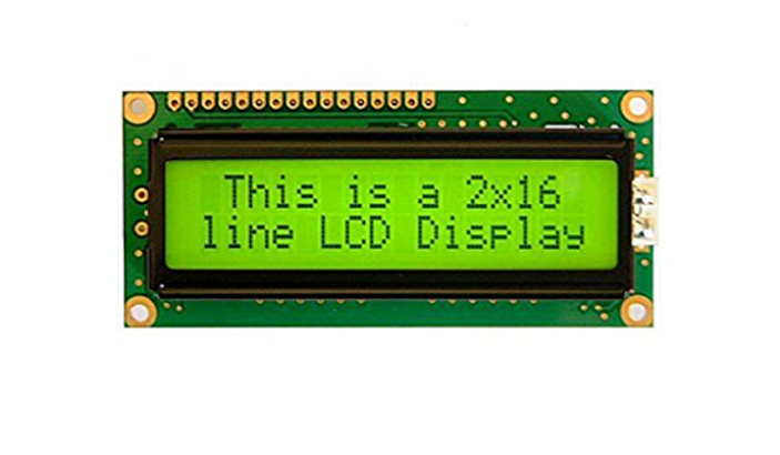
LCD is a display that uses the properties of liquid crystals to produce an image. It consists of an array of pixels that can be individually controlled to produce text and graphics. The most commonly used type of LCD is the character LCD, which displays characters and symbols in a fixed format.
LCD requires a minimum of 7 pins to interface with a microcontroller: RS, RW, E, and 4 data pins. RS (Register Select) and RW (Read/Write) pins are used to select between data and command modes and to control the direction of data flow. The E (Enable) pin is used to trigger the LCD to latch in data. The 4 data pins are used to send the 4-bit or 8-bit data to the LCD.
Interfacing an LCD to 8051 Microcontroller
follow these steps:
1.Connect the power supply: An LCD requires a power supply of +5V and 0V. The +5V can be obtained from the 8051 microcontroller’s Vcc pin, and 0V can be obtained from the GND pin.
2.Connect the control pins: Connect the RS, RW, and E pins of the LCD to the 8051 microcontroller’s GPIO pins. Set the RS pin to 0 for command mode and 1 for data mode. The RW pin should be set to 0 to write data to the LCD. The E pin should be pulsed high and low to trigger the LCD to latch in data.
3.Connect the data pins: Connect the 4 data pins of the LCD to the 4 GPIO pins of the 8051 microcontroller. We are using 4-bit mode for this example, so we only need to connect the 4 least significant data pins (D4-D7) of the LCD to the GPIO pins of the 8051 microcontroller.
4.Initialize the LCD: To initialize the LCD, we need to send some commands to it.
The following commands are commonly used:
a. Function Set: This command sets the interface data length, number of display lines, and font size. The command is 0x28 for 4-bit mode.
b. Display ON/OFF: This command turns the display on or off. The command is 0x0C for display on and 0x08 for display off.
c. Clear Display: This command clears the display and sets the cursor to the home position. The command is 0x01.
5.Write data to the LCD: To display data on the LCD, we need to send the data to it. We set the RS pin to 1 to select data mode and the RW pin to 0 to write data. We then send the data in 4-bit mode, one nibble at a time. We pulse the E pin high and low after each nibble to latch in the data.
#include <reg51.h>

#define RS P1_0
#define RW P1_1
#define E P1_2
#define LCD_PORT P2

void delay(unsigned int count) {
  unsigned int i, j;
  for(i=0; i<count; i++) {
    for(j=0; j<1275; j++);
  }
}

void lcd_cmd(unsigned char cmd) {
  LCD_PORT = (LCD_PORT & 0xF0) | ((cmd >> 4) & 0x0F);
  RS = 0;
  RW = 0;
  E = 1;
  delay(5);
  E = 0;
  delay(5);
  LCD_PORT = (LCD_PORT & 0xF0) | (cmd & 0x0F);
  E = 1;
  delay(5);
  E = 0;
  delay(5);
}

void lcd_data(unsigned char data) {
  LCD_PORT = (LCD_PORT & 0xF0) | ((data >> 4) & 0x0F);
  RS = 1;
  RW = 0;
  E = 1;
  delay(5);
  E = 0;
  delay(5);
  LCD_PORT = (LCD_PORT & 0xF0) | (data & 0x0F);
  E = 1;
  delay(5);
  E = 0;
  delay(5);
}

void lcd_init() {
  lcd_cmd(0x02);
  lcd_cmd(0x28);
  lcd_cmd(0x0C);
  lcd_cmd(0x06);
  lcd_cmd(0x01);
  delay(5);
}

void main() {
  lcd_init();
  lcd_cmd(0x80);
  lcd_data('H');
  lcd_data('e');
  lcd_data('l');
  lcd_data('l');
  lcd_data('o');
  lcd_data(',');
  lcd_data(' ');
  lcd_data('W');
  lcd_data('o');
  lcd_data('r');
  lcd_data('l');
  lcd_data('d');
  while(1);
}
Code explanation
In this code, we define the RS, RW, E, and LCD_PORT pins using #define statements. We also define a delay function to add some delay between the execution of each instruction. The lcd_cmd() function is used to send commands to the LCD, and the lcd_data() function is used to send data to the LCD. The lcd_init() function is used to initialize the LCD with some common commands. Finally, in the main function, we call the lcd_init() function to initialize the LCD, and then we send the string “Hello, World” to the LCD using the lcd_data() function. The while(1) loop is used to keep the program running indefinitely.
Note :LCD is connected to the 8051 microcontroller as follows: RS is connected to P1.0, RW is connected to P1.1, E is connected to P1.2, and the 4 data pins (D4-D7) are connected to P2.0-P2.3. You may need to modify these pins depending on your specific hardware configuration.
Conclusion
Interfacing an LCD to an 8051 microcontroller in 4-bit mode is a simple task that can be accomplished with a few GPIO pins. By following the steps outlined in this blog post, you can easily display data on an LCD using an 8051 microcontroller. With this knowledge, you can create a wide range of embedded systems projects that use an LCD for user interaction and
