Optocouplers, also known as opto-isolators, are electronic components that provide electrical isolation between two circuits by using light to transfer signals. Optocouplers are commonly used to protect sensitive electronic devices from voltage spikes, reduce noise and electromagnetic interference, and provide isolation in high-voltage applications.
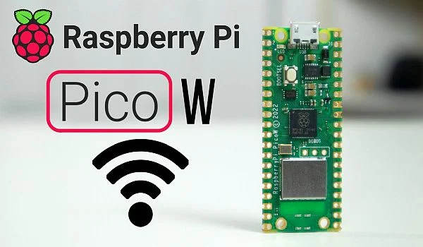
Raspberry Pi Pico is a popular microcontroller board that features a powerful Arm Cortex-M0+ processor and a range of peripherals, including GPIOs, I2C, SPI, UART, and more. The Pico is an excellent platform for learning about microcontrollers and for developing a wide range of projects.

In this blog post, we will discuss how to interface an optocoupler to a Raspberry Pi Pico board. We will cover the basic theory behind optocouplers, the different types of optocouplers available, and how to connect an optocoupler to the Pico board.
Understanding Optocouplers Optocouplers are essentially a combination of a light-emitting diode (LED) and a photodetector. When a voltage is applied to the LED, it emits light, which is then detected by the photodetector. The photodetector then converts the light into an electrical signal, which is isolated from the input circuit.
Optocouplers are available in different configurations, including Darlington, triac, and transistor optocouplers. Each type of optocoupler has its own set of advantages and disadvantages, and the choice of optocoupler will depend on the specific application.
Connecting an Optocoupler to Raspberry Pi Pico To interface an optocoupler to a Raspberry Pi Pico board, we will use the transistor optocoupler configuration. This configuration is ideal for switching low-current DC loads, such as relays, LEDs, and motors.
The following steps will guide you on how to interface an optocoupler to a Raspberry Pi Pico board:

Step 1: Gather Components The following components are required for interfacing an optocoupler to a Raspberry Pi Pico board:
- Transistor optocoupler (e.g., 4N35)
- Resistor (e.g., 330 ohms)
- Jumper wires
- Breadboard (optional)
Step 2: Connect the Optocoupler to the Pico Board The following steps will guide you on how to connect the optocoupler to the Pico board:
- Connect the VCC pin of the optocoupler to the 3.3V pin of the Pico board.
- Connect the GND pin of the optocoupler to the GND pin of the Pico board.
- Connect the Anode pin of the optocoupler to GPIO pin of the Pico board.
- Connect the Cathode pin of the optocoupler to a 330-ohm resistor.
- Connect the other end of the resistor to the GND pin of the Pico board.
Refer a Circuit

