Understanding the Clock in TM4C123 Series Microcontroller
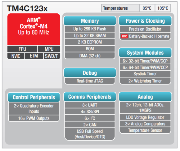
Understanding the clock structure of Tiva C Series Microcontroller TM4C123
Understanding the clock structure of Tiva C Series Microcontroller TM4C123
How to Build projects for tm4c123gh6pm Microcontroller from Tiva C Series using the Tiva C Launchpad
