Clock in TM4C123
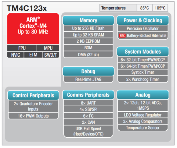
The clock in Tiva C Series Microcontroller TM4C123 is explained here.
The clock tree may look a bit scary at first, but practically its very simple. The actual clock tree of the TM4C123 microcontroller is like this
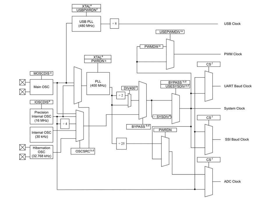
As we can see in the above diagram. There are 4 main sources of the Clock frequency
- Main Oscillator: This is the crystal that we can connect externally to the MCU. Depending on which crystal value we’ve used the system clock will change
- Precision Internal Oscillator (16MHz): This is an internal precision 16MHz clock with 1% tolerance in values
- Low Frequency Internal Oscillator (30KHz) : the speed is very low, suitable for deep sleep modes
- Hibernation clock source
Now these are the main clock sources, but we can see many different blocks there as well. We need to understand how the clock is derived to understand more.
The important thing to understand in the Tiva C Series microcontroller is almost the entire system works on Single Clock source (except the USB)
This single clock source can be coming from one of the main clock sources OR it can come from the Internal PLL.
What it means is this
- TM4C123 Can be directly Clocked with External Crystal between 0-50MHz crystal, here we disable PLL
- TM4C123 Can be directly Clocked with Precision Internal Oscillator, this value is 16MHz with 1% +/-, here we disable PLL
- TM4C123 Can be directly Clocked with Internal Oscillator which works at 30Khz having +/- 50% of precision, here we disable PLL
- TM4C123 Can be directly Clocked with Hibernation Crystal Oscillator, here we disable PLL
- AND we can also decide to use the internal PLL which can use any of above as its clock source and it’ll generate its own different clock source
When we use PLL, we can increase the clock speed of the TM4C123 manyfold.
The TM4C123 has a 400MHz PLL. Means it can generate a maximum of 400MHz depending on what is the applied input clock to the PLL. As told before the PLL can accept clock from only 2 of the above-mentioned sources.
- External Crystal
- Precision Internal Oscillator
Now enough of theory, lets try to understand from practical point of view. Any embedded designer would want to use a proper external crystal for the microcontroller to work properly. So here the selection of the crystal value decides what’s the clock going to be.
So here we’ll also assume that we’re going to use PLL, because hey, why NOT? If we’re going to get higher speeds at lower crystal frequency, why not. So lets establish that we’re going to use
- External Crystal
- PLL
Now what frequency the PLL generates which is used by the entire MCU? This is given by a table in the datasheet of TM4C123 microcontroller.
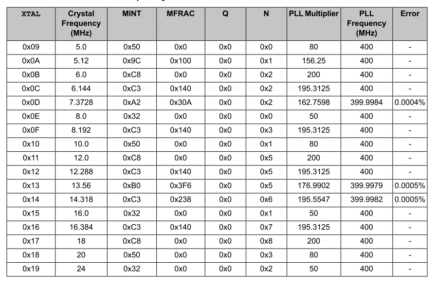
As can be seen from above table, we can deduce that
- If we use 16MHz external crystal, the PLL will generate a 400MHz Clock
But, It DOES NOT MEAN that system is operating on 400MHz, TM4C123 can’t run on 400MHz, our maximum TOP clock speed is 80MHZ.
So unlike the PLLs of other micros like STM32s, instead of multiplying input clock source, it is divided by System Divisor, Sysdiv to obtain desired clock speeds.
So what’s next?
The VCO will by default divide this PLL clock by 2. So what we get at the output is 200MHz
Now the SYSDIV bit in RCC register decides what operational clock we get.
e.g. If the SYSDIV is set to 5.
Lets assume Crystal is 16MHz and hence PLL output is 400MHz
So the VCO output = 200MHz
AND
SYSDIV = 5
So System clock = 200 / 5 = 40 MHz
We have a combination of SYSDIV and SYSDIV2, using combination of both, we can generate upto maximum of 80MHz for operation of TM4C123 Microcontroller
Common examples with Tiva ware library parameters are here
- SYSCTL_SYSDIV_5 = 40MHz
- SYSCTL_SYSDIV_4 = 50MHz
- SYSCTL_SYSDIV_10 = 10MHz
- SYSCTL_SYSDIV_2_5 = 80MHz
Hope it clarifies the concepts. About the SPI clock and other peripheral clocks, I’ll add further inputs as they come to mind
Generating 1 microsecond and 1 milliseconds delay on TM4C123
tivaware has lots of API functions which are used for various purposes. Out of them is a function
void SysCtlDelay(uint32_t ui32Count)
This function provides a delay by executing a simple 3 instruction cycle loop a given number of times. It is written in assembly to keep the loop instruction count consistent across tool chains.
It is important to note that this function does NOT provide an accurate timing mechanism. Although the delay loop is 3 instruction cycles long.
But for our practical purposes we need a crude 1 milliseconds and 1 microseconds of delay multiple times during the programming. So I have done some computations and created these 2 functions for our use
void delay_ms(uint32_t ui32Ms) {

	// 1 clock cycle = 1 / SysCtlClockGet() second
	// 1 SysCtlDelay = 3 clock cycle = 3 / SysCtlClockGet() second
	// 1 second = SysCtlClockGet() / 3
	// 0.001 second = 1 ms = SysCtlClockGet() / 3 / 1000

	SysCtlDelay(ui32Ms * (SysCtlClockGet() / 3 / 1000));
}

void delay_us(uint32_t ui32Us) {
	SysCtlDelay(ui32Us * (SysCtlClockGet() / 3 / 1000000));
}
These functions are tested on my tiva C series launchpad and are working fairly good. A testing with Scope will reveal exact timing but its good for basic purposes
