8 Tools you must have for your hobby Electronics Lab

Know about a selection of must have tools for your hobby electronics lab
Know about a selection of must have tools for your hobby electronics lab

What is DC Power Supply? All circuits and gadgets and everything that is running on Electrical energy requires some particular Voltage and Current. There are 2 type of electrical powers available, called AC Supply and DC Supply. AC Supply is the one which is available to us from our Home Socket, this is a very … Read more

LED’s are perhaps the most interesting electronic component that we use in circuit. LED’s are (Light Emitting Diode) components which can emit a specific light. It can be RED, Green, Blue or Yellow. LED’s require very less voltage to turn ON (typically 3v) and they have a very long life. We see LED’s in power … Read more
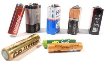
Every electronic circuit, project or gadget like our mobile phone or the speakers that we use, require electrical power to function. We can draw this required electrical power from our mains outlet using a power supply. When we want mobility and freedom from wires, we have to use a portable powerhouse. These are DC power … Read more

How to use breadboard. This is a detailed breadboard tutorials for all those who are new to electronics and trying to use breadboard for their prototyping projects
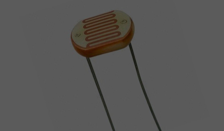
A Light Dependent Resistor (LDR) is also called a photoresistor. The passive component is basically a resistor whose resistance value increases when the intensity of light decreases. The resistor behaves depending upon the amount of light falling on it. In general, LDR resistance is minimum (ideally zero) when it receives a maximum amount of light … Read more

Transistor is perhaps the most important of electronic components because of which all modern electronics works. Therefore It becomes not only important but also mandatory to know what is transistor and how transistor works. A transistor is a semiconductor device commonly used to amplify or switch electronic signals. It’s a Device with three terminals where … Read more

Speakers come in all shapes and sizes, enabling you to listen to music on your mobile, tablet, laptop and home audio system, enjoy a film at the cinema or hear a friend’s voice over the phone. In order to translate an electrical signal into an audible sound, speakers contain a permanent magnet and an electromagnet, … Read more

Resistors are those tiny little electronics components which opposes the flow of electric current. Whenever we try to build a small circuit, if a resistor is added into that circuit, the job of resistor is to resist (or oppose) the current flow. The value of resistance offered by a resistor never changes. Resistors are passive … Read more
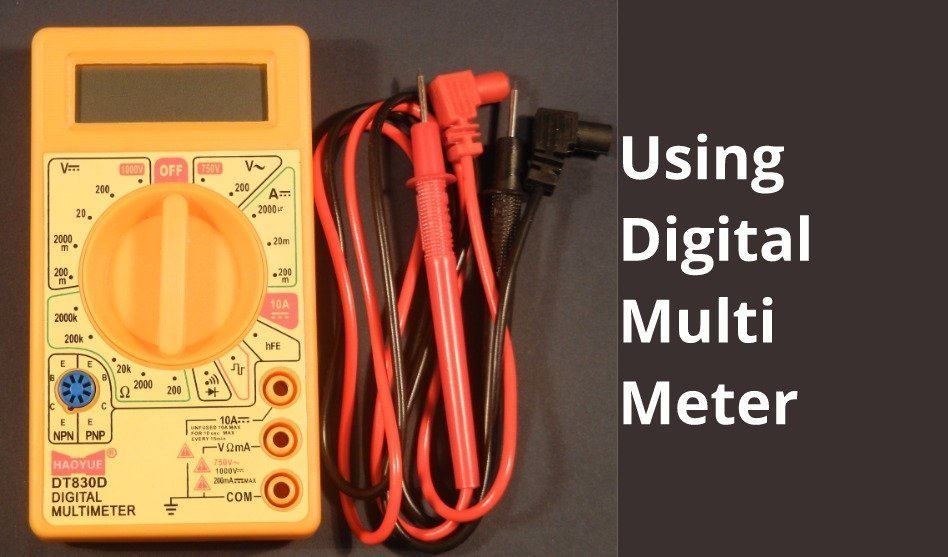
How to use the digital multimeter. This tutorial is about the most basic electronic instrument everyone in electronics engineering needs

This is a short tutorial about how LDR Works and what are the basics of light dependent resistor which is commonly used as sensor in many electronic projects
Learn how a basic electronics circuit is built