Making circuits on a board requires lots of time and special skills. For long time, scientists and engineers rely on a simple method to develop any circuit. In this technique, circuit is built on something called breadboard!!! Confused? Actually a bread board is a rectangular board which is having lots of HOLES to place electronic components in it. The holes in bread board are interconnected in such a manner that makes connection of components easier. Still for making additional connections, we need simple single strand wire. This is the wire which has only one thick thread inside the insulation. Look below pictures for knowing about bread board and making a simple LED circuit on breadboard
It has ten rows (lines) of holes in the main area. Each line has 64 holes. There are also two power lines at the top and two at the bottom.

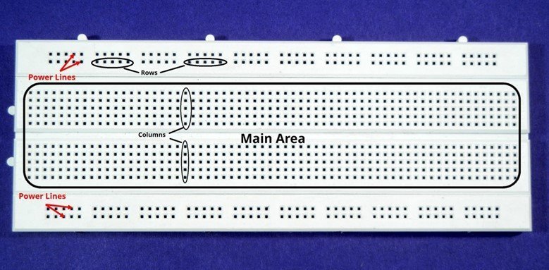
As you can see in above image. The bread board is basically a rectangular box, made up of plastic material. The breadboard, as shown in the above picture is having lots of holes which can house components inside it. All we have to do is understand the internal connections of breadboard and insert components into it.
The internal structure of breadboard is also very simple. As in there are lots of holes to the breadboard, there must be something which interconnect the components. If we consider the above picture; we can see there are columns of 5 Holes each and there are Rows of 5 Holes each. The rows are spared in the top of breadboard and the bottom of breadboard. The columns occupy the entire middle area of breadboard. The columns are interconnected vertically, and the rows are interconnected horizontally. See below picture for reference
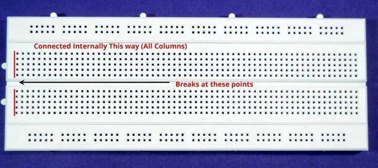
As you can see in above picture, the red vertical line shows the interconnection of holes present in one Top column and one in bottom column. There is a break as shown in the picture. So the vertical column is only connected to five points in one column and does not connect with the to the other column down the break.
Similarly, the rows are also interconnected as shown in below picture
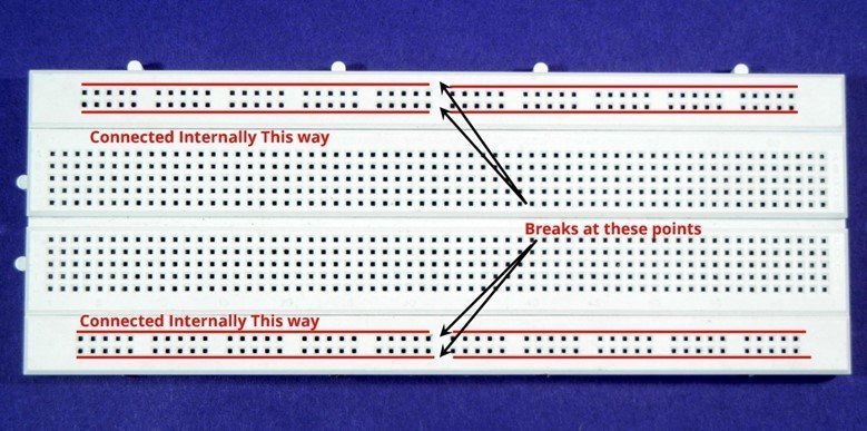
There is a break in row connections also. Also the rows are connected in straight horizontal line as shown by red color in above image so these points don’t intersect with the line parallel to it. So we can use these lines for Supply and GND both on the top of breadboard as well as at the power of breadboard. Hence they are also called as power rails or power lines of breadboard.
Using Breadboard
Now using this interconnected board of holes arranged in rows and columns, we have to construct a real circuit. You can insert any component having leads in breadboard just like the resistor is inserted in below figure.

Make sure that the resistors both leads are inserted in 2 different columns and not in the same column. If a component is inserted in same column, it will get shorted.
To make interconnections on Breadboard among components we use a special type of wire. This is called single strand wire. It’s the wire which is having only single core or single thread which is thick enough to get inserted in breadboard. Look below picture.
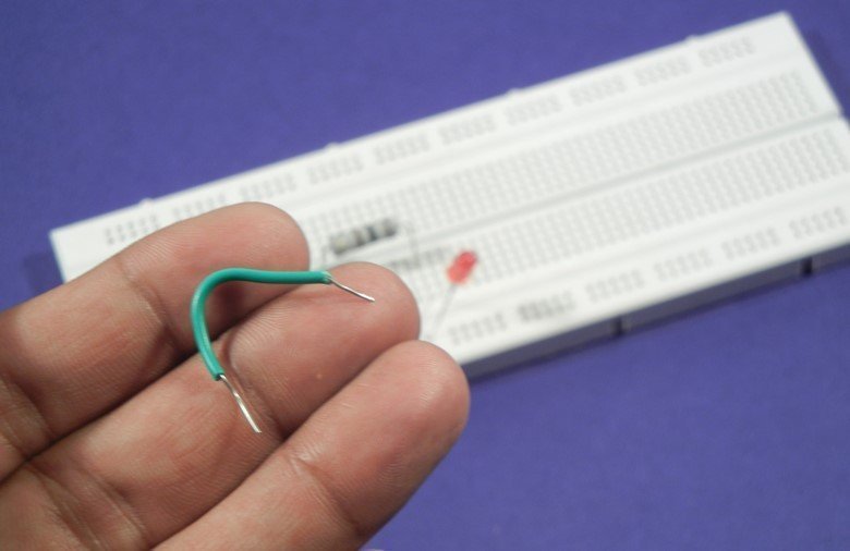
We’ve to cut the wire in required size and strip the both ends of wire to make it easier to get inserted into a breadboard. This wire can be used to connect one lead of a component to the other component forming a circuit. Similarly we can construct entire circuit of components on breadboard and interconnections with these types of wires.
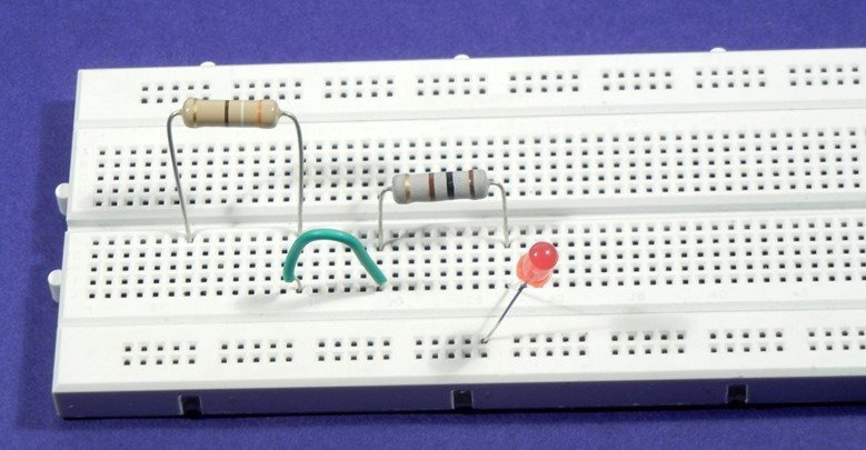
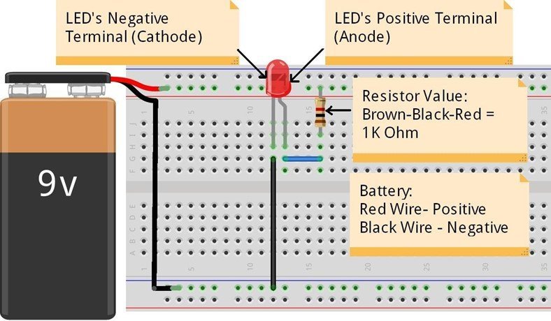
In above picture, you can see, the two resistors leads are connected using this single strand wire. You can use the horizontal power rails to insert the leads of component which are either going to supply voltage vcc or the ground terminal. In above circuit, we’ve connected LED to the horizontal power line. Take a close look over LED in below picture.

IC’s with bread board
Inserting and using electronic components is fairly easy, now we’ll see how to use IC’s on breadboard.
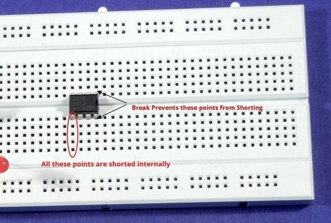
As you can see the first picture, there is a break in the 2 vertical columns of breadboard. This break is there to facilitate the use of IC’s on breadboard, carefully, we can insert IC’s of any size into the breadboard using this break rail without shorting any of its pins.
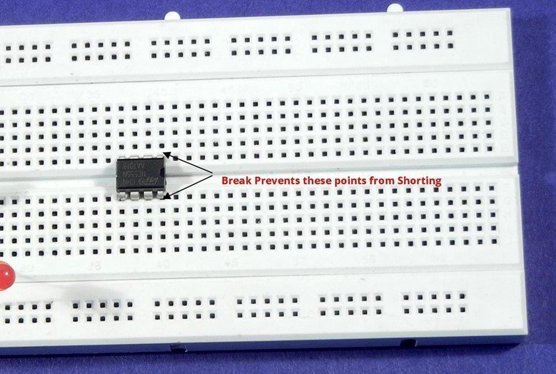
Above picture shows how IC is connected. Now as you see, we have 5 holes in one column, and after inserting IC, we have 4 holes vacant for every IC pin to make interconnections. We can insert wire anywhere from these four points to get a connection with that particular pin of IC
Now below image shows how a small circuit can be built

From above two images it’s clear that there are plenty of pins available for wiring and interconnections with Integrated circuit.
Make sure you insert all the components properly and give the power correctly. Below shows a complete image with all the required components and power. This image is animated.